Simulating the 555 IC with LTspice
Wednesday, March 26th, 2008Ron Fredericks writes: I was designing a simple CMOS timer circuit around a 555 chip this evening. It might be the heart beat for a new digital volume control I have been thinking about. Normally I look for my breadboard and parts box but this time I thought I would try out Linear Technologies LTspice/SwitcherCAD III workbench instead.
SwCAD III First Time Use
The tool is free and comes with a lot of support. I downloaded the software and installed it very easily on my Windows XP PC. It includes a graphical schematic design tool with lots of ready made simulated components, including an NE555 for my initial project. Designing the circuit with the built-in CAD tool works very intuitively. While the LTspice simulation took a bit of head scratching before it worked for me.
I was able to configure and run the simulation using the drop down tools menu and the little “running person” icon on the tool bar. But all I could get out of the simulation was a black screen with voltage and timing ticks along the left and bottom edges. So my first problem was in realizing that the visual display would remain black and traceless until I put the mouse cursor over a wire then click. When the little instrument probe showed up as my mouse icon, I realized what was going on here. With the mouse click, waveform tracings would appear in the black panel.
My second problem was that the circuit would not oscillate. Not good for an oscillator design. First, I forgot to connect the 555’s threshold + trigger pins to the R2-C2 node using the wire tool. But still no oscillation, just flat line traces were observed. Now I already know that getting circuits to oscillate follows Murphy’s Laws: Oscillators remain stable, Amplifies and Buffers oscillate, whenever possible. I found a note on the Old School Hacker blog with a fine solution. You must simulate the circuit with a power supply starting from 0 volts rather than just have an instant on Vcc power supply.
In hind sight dah, its the initial transient response from the circuit’s components that kicks the oscillator into oscillating.
After a little practice I improved the schematic diagram with the use of named nodes and seperation of the temporary load resistors R3 and R load from the more permanent circuit components. The load resistors are just place holders for a real load to be added to the circuit schematic next. Look for my next blog post on this subject.
Finally, I used the cursor measurement facility built into the LTspice window (trace window). With this feature, I was able to make “real” measurements on the waveform for frequency and duty cycle.
Circuit
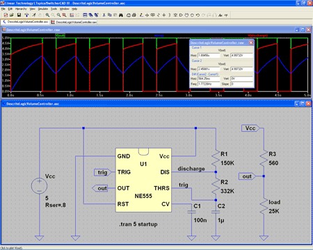
Here is what I was able to generate using the LTspice/SwitcherCAD III tool:
View larger image>
Download 555 Astable Flip-Flop Schematic Circuit Diagram>
Referring to the figure above:
Green Trace -> Output (IC 555 pin 3)
Blue Trace -> Trigger / Threshold (IC 555 pins 2 & 6)
Red Trace -> Discharge (IC 555 pin 7)
The Astable Multivibrator
The circuit shown above will trigger itself and free run as a multivibrator. The capacitor C2 charges through resistors R1 and R2 yet discharges through R2 only. Thus, the duty cycle (D) may be precisely set by the ratio of these two resistors. The capacitor charges and discharges between 1/3 Vcc and 2/3 Vcc. But the initial pulse charges C2 starting from 0 Vcc and so this first pulse duty cycle is unique. Since the charge rate and the threshold levels are directly proportional to the supply voltage Vcc, the frequency of oscillation (f) is independent of the supply voltage.
| Frequency Calculation | Duty Cycle Calculation |
|---|---|
C_2}") |
 |
 ohm farads}") |
 |
| Measured = 1.8 hertz | Measured = 0.60 |
Where: is frequency in hertz is frequency in hertz is capacitance in farads is capacitance in farads is resistance in ohms is resistance in ohms |
Where: is duty cycle is duty cycle is non-zero output duration is non-zero output duration is the period of the output is resistance is the period of the output is resistance |
Reference
- 555 Datasheet icm7555.pdf
- Linear Technology’s SwitcherCAD™ III Landing Page
Technorati Tags: Ron Fredericks, schematic, LTspice, SwitcherCAD III, simulator, Spice, CAD
=a^2+2ab+b^2")
 is defined as a
 is defined as b